TOR goal 3 ter-omega
TOR (Target of Ruslan)
Current goal 4096 k-omega

CSWS-MAN-010, Issue 2
April 2024
- TOR goal 3 ter-omega
- 1 INTRODUCTION
- 2 MOBILE PHONES OF “TOR” SERIES
- 3 FULL-DUPLEX TRANSMISSION
- 4 NETWORK
- 4.1 RTOS environment formation
- 4.2 Subnets
- 4.3 The use of granular approximation
- 4.4 Channel digestion
- 4.5 RTOS synchronization with the OS platform
- 4.6 Routing paths inspection
- 4.7 Off-line feeders commutation in RTOS
- 4.8 IRQ interrupts the function
- 4.9 Virtualization
- 4.10 Media network creation using RTOS
- 4.11 Type-C port
- 4.12 Types of signals
- 5 RTOS
- 6 VIRTUAL CONSOLE PORT
- 7 STRUCTURE OF THE LASER PORT
- 8 MANAGEMENT INFORMATION BASE (MIB)
- 9 THE EXTENDED WORK
Copyright
Copyright © 2024 Compositor Software. All rights reserved.
No part of this publication may be reproduced or distributed in any form or by any means, or stored in a database or retrieval system, without the prior written agreement with Compositor Software.
Disclaimers
This document is an essay style writing consisting main modules description in a form of chapter-by-chapter basis. This doesn’t imply the direct description of each module and its performance neither the complete documentation of all the heavy reconnaissance forwarder “Tor” parameter features. This document may be seen in this regard as a solution to solve different problems using fully automatic self-explained signal chain with little digressions to cover basic parameter features.
About this Document
This document is the hardware manual for TOR aquiring.
For the installation and setup instructions, please refer to the Tank 3 Installation Manual.
Audience
This document assumes a working knowledge of Ethernet hardware.
1 INTRODUCTION
The real-time network operating system Compositor is based on the extension of parameter attributes of the RAD96 kernel and includes the following virtual network functions (VNF):
- OSI vScanner: RIPv1, RIPv2
- OSI vAggregator: OSPF, OSPFv3
- OSI vRouter: BGP, RIPng, EIGRP
These functions form a wireless data transmission environment where they can be connected to the AVP interface to work with an internal kernel extension database consisting of 10171 routing tables. Work with the host operating system on which the Compositor NRTOS runs is carried out through a local database, allowing you to organize a connection environment for these extensions as network devices (NIC, network interface controller) and establish a local connection to them. Based on this, Compositor NRTOS allows you to make sets of configurations of virtual operating systems with different devices and save them in presets for later continuation of work with these environments.
The main tasks of Compositor NRTOS are:
- Equality of audio frequency modulation and radio frequency modulation;
- Proof of Carson’s rule;
- The effect of using beatings for signal modulation;
- Study of the problem of irregular signal sampling rate;
- Application of frequency modulation on low-voltage power supply networks (e.g. telephony);
1.1 Thesis
The periodic time determined by the AC frequency is the current moment of time or an antiderivative hyperbolic function. This system is based on periods of rotation of Euler angles, multiples of 1(2):1:2. Compositor NRTOS number system uses a 64-bit representation, the base of a logarithmic function is power of two.
An original function, which is the basic function of Compositor NRTOS:
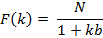
The graph of the function is hyperbola.
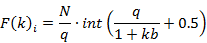
Compositor NRTOS is built on the basis of the law of frequency modulation (FM) and uses it to transmit data on an on-air network. FM is characterized by three parameters, such as central frequency, modulation frequency and modulation index. These three parameters describe a wave phenomenon with compression and wave expansion in the temporal representation. With simple frequency modulation by two sources of sinusoids, there is a number of frequencies k calculated by the formula:

Where, k – number of side-bands, I – modulation index.
To separate harmonics when multiplexing FM channels in the upper and lower side-bands, Compositor NRTOS uses a cascade of two Butterworth filters of the 2nd order.
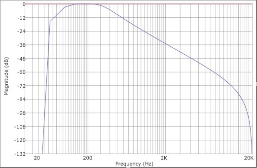
Fig. 1 – Butterworth 2nd order bypass filter
Thus, the bandpass filter characteristic becomes 12 dB per octave (total 24 dB) and a filter pass-band is equal to 3/4 of the modulation frequency. The filter was created using bilinear transformation and is recursive. Mathematically, it can be represented as follows:

In FM, the upper side-band (USB) and the lower side-band (LSB) are formed. The amplitudes of frequencies in the side-bands are displayed by the Bessel function and are the Bessel functions of the 1st order. The number of negative side-bands is equal to the number of positive side-bands. Negative side-bands are divided into even and odd. Odd side-bands begin with a negative phase, and even side-bands begin with a positive phase.
1.2 Main part
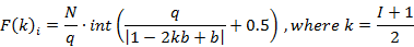
The segment of the virtual protractor from 0 to 2π is four planes of the Cartesian coordinate system. Then each of the frequency modulation harmonics can be displayed on the protractor, comparing it with the center frequency, and present it on a spiral passing along the surface of the truncated cone with a diameter of each spiral revolution equal to 1024 Hz. Frequency values for different ratios of modulation frequency to center frequency, which are determined by a single parameter of the divisor b, correspond to different rotations of the spiral, which is explained by the expansion and narrowing of the values of the desired function. Then, taking the window of synchronous analysis of the non-harmonic spectrum (SANS) as a deviation, and presenting it in Hz, we get that each harmonica on the spectrum is lined up in a series equal to positive frequencies:
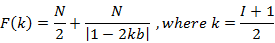
For negative odd frequencies:
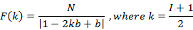
For negative even frequencies:
N – SANS window
b – divisor ratio of modulation frequency to center frequency
Figure 2-4 shows graphs of the function for the divisor b = 3:

Fig. 2 – Function for positive side-bands
Fig. 3 – Function for negative even side-bands

Fig. 4 – Function for negative odd side-bands
The deviation is 1024 Hz, which corresponds to 1024 samples of the SANS window. It follows from the graph in Figure 3 that the amplitudes of negative bands are multiplied by -1. A positive spectrum when a low center frequency is used, which stays from the base (0 Hz) less than the modulation frequency is possible only when taking the negative frequency module. To do this, in Compositor NRTOS at z=0.5, the center frequency varies from 37.9259 Hz to 73.8817 Hz while maintaining the deviation unchanged and equal to 1024 Hz. Temporal dependences at such a center frequency and deviation correspond to the maximum purity of the perceived signal.
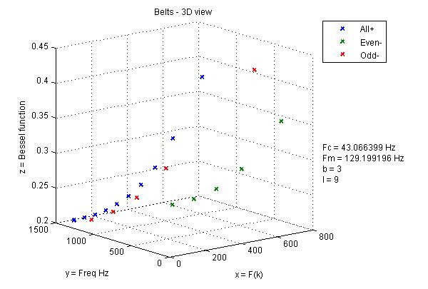
Fig. 5 – Branches of the function in 3-dimensional space
Deviation in frequency modulation is determined by the formula:

Since the frequencies turn around zero, the deviation is less than 1024 Hz for negative side-bands. It follows that the SANS window is equal to 1024 samples.
The center frequency of the periodic signal during the Fast Fourier Transform (FFT) is determined by the formula:

FFT divides the spectrum into k channels, which are between 0 to N/2. N/2 * f0 channel sets the Nyquist frequency, which characterizes the upper sampling limit. My method is not based on static reference to the center frequency, as in the phase vocoder, because I use a variable center frequency, and the modulation frequency does not change, so the parameter b cannot be a multiplier, but is a modulation frequency divisor, which helps to find the desired center frequency and allows you to determine the communication lines using buffer collisions. This is confirmed by the following:
I assume that 44.1 kHz is the first four prime numbers of a decimal progression:

I use the same representative model for 1024 samples:

Compositor NRTOS allows you to perform a SANS in the value of the divisor b = 2, but for this the signal sampling frequency must be 58254.2336 Hz.
The modulation frequency remains unchanged and is equal to 113.778 Hz at I = 9, only the ratio of the modulation frequency to the central frequency, namely the divisor, changes.
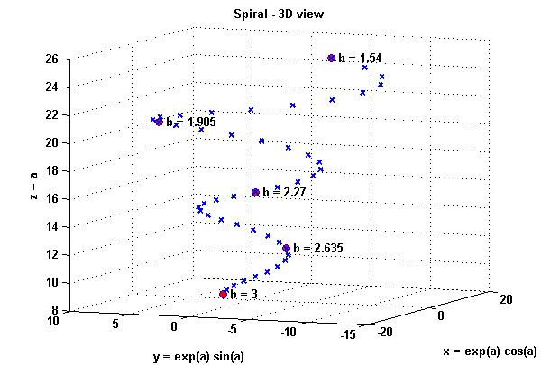
Fig. 6 – Dependence of the divisor on spiral rotation
The entire metric system can be represented as a virtual protractor, where the inner circle corresponds to the radians, and the outer one has frequency gradations and values of the divisor. Then, in order to match the values of the divisor and frequency bands, it is necessary to build the entire metric system in a spiral, where the wide coil corresponds to the values of frequencies and phases at the divisor b = 1.54, and the narrowest coil of the spiral corresponds to the value of phases and frequencies at b = 4. Accordingly, the function varies with the change of the divisor. Frequency bands k correspond each to its own phase value and expressed in the time segments of the SANS window (radians). For ease of programming, Compositor NRTOS uses digital signal samples. Each frequency filtered from the frequency modulation spectrum is characterized by a pass-band frequency, which is set as 3/4 from the modulation frequency. This value is not selected randomly and corresponds to the bandwidth (Fm/2)*1.5. This bandwidth is selected based on the divisor b = 2. In this case, the negative frequencies wrapped around zero coincide with the positive ones. Sufficient bandwidth is equal to Fm/2, but I use an extended spacing and multiply the bandwidth by another 1.5 to compensate for the loss of -3 dB at the filter cut-off frequency. The bandwidth for z=0.5 is 85.3333 Hz and selects the harmonic for which the filter is currently configured.
Thus, the signal chain of the Compositor NRTOS is as follows: FM arising from the modulation of one sinusoidal oscillator by another is divided into a number of frequency bands, according to the function and formula for determining frequency modulation side-bands. These frequency bands are reproduced at a speed set by one of three ways: period time in milliseconds, network number in decimal value and angular velocity (ω). All values can be converted, and formulas are used for this:
From the decimal representation to ω:

where θ – network number.
From ms to ω:

From ω to the decimal representation:

Each of the frequency bands holds a certain amount of time equal to the step function, where the increase in values occurs step by step.
The steps of a function encased in a window function that contains several cycles of the upper or lower side-band. This allows you to use SANS to determine the desired value of the center frequency of the transmission channel.
The next in the signal path is the module of signal separators into two streams. For the upper zones of the frequency range, nonlinear transformation by wave deformation of the signal is used, and for the lower frequency bands of the spectrum, physical modeling of the waveguide is used, which divides the reproducible frequencies into optical ports and electric ports with PoE support. This allows the reconstitution of the signal spectrum. The optical port parameters are selected according to the nonlinear propagation of the medium according to the rule 1/f.
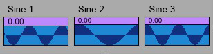
Fig. 7 – Phases of IRQ interrupter flags
According to Chebyshev polynomials, Compositor NRTOS calculate transmission functions for various radio spectra with even and odd harmonics. The master generator, whose period is equal to the period of the SANS window, synchronizes wave tables that reproduce the values of the three functions presented. Three sinusoidal signals at the zero-crossing intersection are the IRQ (Interrupter Request) flag sequences of the interrupter. The zero-crossing of the first sine wave can occur both at 0 and π at one period for a window cycle and on 0, π/2, π, 3π/2 at two periods for a window cycle. For the second sine wave whose flag values fall on π/2 and 3π/2, the phase value is added to x = 90 degrees. For the third sine wave, the values of the flag fall on π/4, 3π/4, 5π/4, 7π/4. Phases in the Compositor NRTOS are recorded in normalized values from 0 to 1, which corresponds to the following table:
Phase | ||
Degrees | Radians | Normalized values |
0° | 0 | 0 |
45° | π/4 | 0.125 |
90° | π/2 | 0.25 |
135° | 3π/4 | 0.375 |
180° | π | 0.5 |
225° | 5π/4 | 0.625 |
270° | 3π/2 | 0.75 |
315° | 7π/4 | 0.875 |
360° | 2π | 1 |
The signal of three sine waves in values from 0 to 2π represents Euler’s angles. To rotate the flows of spherical space in the Compositor NRTOS, these angles (x, y and z) are transformed into a quaternion, which consists of a real (scalar) part and x, y, z as an imaginary part. Compositor NRTOS displays this process graphically using a ring and flow points, which indicate the position of the server in the distance-vector system.
When changing the divisor b, the values of the function expand and narrow, thereby combining the antiderivative function and the standard mesh expressed in base 8. This approach guarantees the coincidence of certain phases of the frequency bands when divisor b = 3 with the grid on base 8 in the following values:
Positive bands – 5th frequency on π/8, 1st frequency on π/2.
Negative odd bands – 3rd frequency on π/4, 1st frequency on π.
And only negative even side-bands do not coincide with the grid on base 8.
The next aspect is the statistical property of the system. If you take for abstraction that the signal is continuous and there is arbitrarily infinite time, then the SANS is applicable. Since the whole row is a sequence, the window is repeated recursively and can theoretically be reproduced indefinitely.
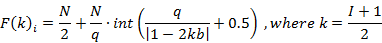
The time segment of the window is divided into segments by step integral. Granular synthesis is carried out by a derivative of a function that combines granules with a rounding mesh of a function based on base 8. N samples are used to indicate the phase, and N Hz is used to indicate deviation equal to the maximum bandwidth of the tone frequency channel. Signal components are played sequentially, one after the other. The values of the antiderivative function are rounded to a mesh on base 8 using the derivative of the function.
Derivative for positive frequencies:
Where q is the quantization mesh.
Derivative for negative odd frequencies:
Derivative for negative even frequencies:
To maintain the general characteristic of the signal spectrum, according to the nonlinearity of the function corresponding to the hyperbola graph, the spectrum of the resulting signal in the Compositor NRTOS is approximated by the characteristic of the two-pole band-pass filter of the 2nd order.
1.3 Conclusion
Compositor NRTOS considers a number of frequencies both as an arithmetic progression and as a spectrum band that complies with Carson’s rule. This rule postulates a sufficient number of harmonics in the FM spectrum equal to I + 1. According to Chowning, the spectrum of the FM audio signal is equal to d = I * Fm (where d is deviation, I is the modulation index, and Fm is the modulation frequency), which gives the spectrum less than according to Carson’s rule. If we consider FM audio signal from the point of view of the formula above, then for audio frequencies at a deviation of 1024 Hz, you get a spectrum with a upper side-band maximum frequency equal to 1058.13 Hz, which at a modulation frequency of 102.4 Hz corresponds to the desired spectrum of 1024 Hz (if we count from Fc = 34.13 Hz), and when considered as a frequency modulation of radio-signal the upper side-band maximum frequency equal to 1175.7 Hz. I insist on Carson’s rule application to FM audio signal, which postulates a spectrum of 1175.7 Hz in this case for I + 1 harmonics of the signal, while the kth harmonic is not a progression, but an additional frequency at frequency modulation. According to Chowning’s paper, frequency modulation of the audio signal produces a spectrum of 1058.13 Hz, not 1175.7 Hz. So in the spectrum of frequency modulation of the audio signal for I=10 in his opinion there are 10 harmonics. Compositor NRTOS proves that the FM audio signal is also a radio signal transmitting in the ULF-VLF range. This concludes that there are I + 1 harmonics in the FM audio signal, and it complies with Carson’s rule.
2 MOBILE PHONES OF “TOR” SERIES
2.1 Overview
The main property of L1+ “Tor” mobile phone series is a full-duplex signal translation. L1+ “Tor” mobile phone series allow you to transfer the signal without ether interferences, which characterize a duplex transmission. This interference can be a noise of regenerative circuits, which can be difficult to clean with special devices.
Full-duplex transmission gives you the advantage of broadband broadcast of Ethernet signal, which allows you to transfer the routing tables stored in lookup containers with a bandwidth of up to 5 kHz. Since the primary function of the lookup containers is to exchange routing tables, a signal from the server is transmitted on L1+ layers and filtered from the signal components of a duplex digital broadcast. Such components can serve as clicks and noises of the original translation.
2.2 L1+ network layers
Full-duplex virtual optical ports provide the ability for signal transmission in IP network, as well as the terminal messages in the Ethernet at the L1+ layers. The high reliability algorithm is used to transmit routing tables into the network. The routing table allows you to establish a connection with devices in the local network.
2.3 Formation of autonomous systems
Mobile phone without a possibility of routing tables transmission is called the generic phone and is a basic device for subsequent modifications. It should be said that you can search directly in the program code of the mobile phone, and use only that modulations, which are the object of study of original transmission algorithm. In RTOS such search criteria are feeders, built on the derivative of a function, and feedbacks of half-duplex transmission.
Heavy reconnaissance forwarder “Tor” management information base includes device extensions of different profiles. By selecting a routing table in RTOS, you should connect its media through the transmission in one of the virtual PoE ports of heavy reconnaissance forwarder “Tor”. You should connect to the network equipment by RTOS MME extension (routing table). Heavy reconnaissance forwarder “Tor” uses only serial devices, and not the product samples or factory exhibits as feeders that is why virtualization of RTOS network functions integrates easily into existing IP networks.
Feeders’ conductivity is from: z = 2 S – 1048576 S. Feeder is used to receive the original ether, and translation is considered a connection of devices via virtual PoE injector to heavy reconnaissance forwarder “Tor”. Feeders are selected in such a way as to create strong feedbacks when you use full-duplex transmission. In automatic mode, by installing stable random distribution function, heavy reconnaissance forwarder “Tor” mobile phone can give feedbacks with the tuning change of the feeder circuit, i.e. scan the network for broadcast. This way, receiving feedbacks and transmitting them on the L4 layer, you can connect feeders to these devices using the serial method. The types of excitations of these feeders are different. When changing the tuning, L2 feeder gives a strong reaction in the feedback loop of the heavy reconnaissance forwarder “Tor”. Derivative feeders L1-L3 give transparent feedbacks without interference.
2.4 Merging geographical locations
With development of microchips and digital systems at the end of 80th of the last century, the virtual local area networks emerged. VLAN layers and processes are emulated using virtualization method by computer programs. VLAN is a complex multi-fragment system containing different topologies. Such topology frequently have border areas, which are formed on the borders of geographical terrains. They represent a barrier for conducting communications. In contrast to traditional firewalls, this barrier doesn’t have ports and represents structural formation, described by terrain spectrum. It can be represented as a set of collectors physical addresses, forming this district. Physical addresses communicate with each other, forming a route in the area. This route has an Ethernet MAC-table in the form of digital signal with terrains spectrum. Each count of this route is one MAC-address. Address density depends on bit depth and discretization frequency of device’s operation system. For 64-bit wavetable this quantity represents 2^64 physical addresses.
Heavy reconnaissance forwarder “Tor” allows reproducing navigation route over terrain. When you leave a district and enter a new terrain your device inherits it’s spectral map. You can create a finite set of terrains by merging them into one map. For the local interpolation of terrains, it is enough to run the heavy reconnaissance forwarder “Tor” with you. Heavy reconnaissance forwarder “Tor” allows performing communications within an area that is using finite terrains set. Each subset has only one terrain, including all physical addresses for this district. Making a connection with one of the devices of a set, you are making a connection with its subset, which described by routing table. Each routing table describes one of the subsets in current moment of time. Movement of time described by angular frequency and vector height of the exponent curvature. Heavy reconnaissance forwarder “Tor” makes available movements of time from 0.05 to 150 omega and exponent ascension heights up to 17000 meters. The VLF waves sent by Tor propagate up to the boundaries of the nearby cosmos, where communication satellites reside. Each satellite contains a routing table (subset) and group of satellites contains all variants of subsets in different moments of time. That is why satellites responsible for defined variant of EUI-48 finite set. The more satellites with defined subsets, the more Earth map approaches to their set. Heavy reconnaissance forwarder “Tor” digital ether boundary is several decades. That is why it can be used for communication networks deployment behind the boundaries of event horizon.
Using “Tor” you can select a terrain of your virtual local area network and access all devices in the geographical map area. This way, other terrains become available to you in remote location. Entering a local area network in other countries you can synchronize their remote geographical area time code with the home area time-code of the device. The more subsets a set contains, the more accurate is the map on the device.
3 FULL-DUPLEX TRANSMISSION
Heavy reconnaissance forwarder “Tor” mobile phone is designed specifically for the purpose of connecting hardware through the virtual PoE injector and work in the Ethernet. The main purpose of this equipment is to connect to the devices from the management information base (MIB).
3.1 Navigation in the distance-vector system
Navigation in the distance-vector system is carried out with the help of the three Euler angles, corresponding to the Roll, Pitch and Yaw angles. The direction on the location of the device, containing the routing table, is carried out by finding the beats when rotating Euler angles and divisor performs a vector orientation in the range of 1.54 to 4, which corresponds to the different moments of time. To establish the moment of time an Altitude of the vector and the angular velocity is used. 262144-CPFSK (262144-node continuous-phase frequency-shift keying) modulator applied to a moment of time is the phase rotator of the TX and RX ports.
Heavy reconnaissance forwarder “Tor” has a built-in analog subtractive synthesizer, which is achieved by the regeneration of periodic function until self-oscillation on the transmission frequency and distribution of synthesis tones in accordance with 262144-CPFSK modulation.
You can check auxiliary ether on heavy reconnaissance forwarder “Tor” mobile phone. It is used to test for the presence of signals at L1+ layers outside the trunk. For this, synthesizer sequence leak check performed in Schroeder chamber circuit with two independent channels. If you hear pure white noise, it means that auxiliary ether is empty and you can safely organize trunk communication.
3.2 System section
There are three layers in the OSI model available for switching on the heavy reconnaissance forwarder “Tor”: on the L1 layer mobile phone applies the modulation to the event generator in real-time; on the L2 layer device operates as decimator, through the application of the modulation to the signal generator, where the discretization frequency is determined by the divisor; on the L3 layer device is running, keeping the tone of the synthesizer at one frequency. The fourth layer of the OSI model (L4) is not available for the patching of modulation, as it is reserved for the transport protocol. L2 layer operates in a narrowband signal mode, as the sampling of modulation is carried out on the FM generator transmission frequency and varies depending on the z parameter, as well as the setting of subtractive synthesizer.
3.3 Creation of a network environment
The synthesizer, which leaks into the electrical port, organizes the code sequences, which you can broadcast. The cycle of such synthesiser is the imitation of analog synthesizer with the step sequencer and arpeggiator. It is an analog modeling circuit with high order filters. The system passes the sound of this synthesizer, as a regular radio broadcast. In a moment when the synthesizer leaks on the electrical port, the 262144-CPFSK modulation is applied. LAZER application performs modulations for creation of more sustainable feedbacks. Many systems have learned to recognize the pseudo synthesizers and do not perform feedback with their impact. If the feedback loop is not formed, you should turn heavy reconnaissance forwarder “Tor” in L2 mode using fractal antenna application. This mode allows you to set a strong feedback through long-wave amplitude modulation.
3.4 Spectrum analyzer
There is spectrum analyzer available in RTOS. Spectrum analyzer displays the waterfall stream, going from left to right. The display performs averaging by logarithmic function. At the bottom low frequencies are displayed and at the top high frequencies up to the filter cutoff frequency are displayed.
4 NETWORK
4.1 RTOS environment formation
After the commutation of a feeder into the mobile phone, there comes a reaction that looks like the feedback produced by heavy reconnaissance forwarder “Tor”. In the feeders such requests are sent with the Hello status. If the result of feeder request in the switch kernel loop is positive you are contacting the agent. Server has an Ethernet subnet mask. If you load the next hop of routing path to the server through inspecting of its routing table, you can use its subnet. Subnets in heavy reconnaissance forwarder “Tor” mobile phone have color tags and pass the wave deformation through the EUI-48 MAC-address table, giving an access to all subnet masks of the Ethernet. The positive reaction on a feeder cycle reproduction is the Hello status.
Taking the subnet mask of the server, you agree to be bound by its appearance, which is characterized by its name and image. If you are using heavy reconnaissance forwarder “Tor” modulation in the already obtained terrain and move it to the L3 layer holding, by disabling the synthesizer, you must turn the 262144-CPFSK modulation off. At the end of communication you cut the line by reproducing 262144-CPFSK modulation in the L3 layer again. This system works only when z = 16 S. At the other z values rule is still present, but the modes of connection and disconnection sound differently.
4.2 Subnets
With the subnet mask of the server, you can trust using its network. The subnet mask is a selective region in the cycle of routing table, often set as the last sample of 256 address routing table (for example, 255.255.255.0), which masks the useful signal (carrier). Carrier is a signal for transmission of the terminal messages. Network includes images of devices, their routing tables, communication with which performed on the carrier level of the server. Carrier takes the properties of the network routing table and includes the location of all devices in it. You should choose your carrier and the mode of translation performed by the selection of phase and Euler angles in the distance-vector system. Server, to which you connect after the adoption of subnet mask, performs the digestion of all network channels on the band-pass filters comb.
There are two ways to connect to Ethernet: serial and parallel. In a parallel connection you demonstrate your subnet mask through the synchronous insert with a cycle of the routing table and inclusion in the transmission channel at the same time. At the L2 layer signal is transmitted only by the electrical ports. To remove the L2 layer subnet masks you can set the values of their amplitudes at 0.
4.3 The use of granular approximation
Heavy reconnaissance forwarder “Tor” mobile phone central place occupies the 262144-CPFSK modulation, which is applied through the granular approximation. The central flag of IRQ interrupt requests is modeled by a simple granulation. The summarized modulation is applied at the output cascade of the virtual optical port. There is an opportunity to summarize the signal from electric ports on the Type-C port of heavy reconnaissance forwarder “Tor” mobile phone. The multiplier is the central switch, allowing configuring the trunks of the master table. This way, modulation and upper zones of the function pass into the subnet mask. 262144-CPFSK modulation is used for the development of the IRQ flag sequence.
4.4 Channel digestion
Heavy reconnaissance forwarder “Tor” channel uses the combined filters and delay modules, the purpose of which is to create the combined effect and resulting rhythm serves as analog dialing. This rhythm as well as the synthesizer sound is a product of modulation, and has the low modulation frequency besides frequency multiples (its frequency is near 0.05 Hz). This LFO is a trigger for switching channel digestion by a comb and each comb filter assigned to its own channel digestion.
4.5 RTOS synchronization with the OS platform
RTOS runs on macOS 10.6.8 Snow Leopard as low-level embedded operating system. The conductance of virtual PoE injector in Heavy reconnaissance forwarder “Tor” server depends from the feeder selection. You can use up to 7 feeders for changing the conductance of the Type-C PoE port at the same time. Applying feeders, you make work in the emulator of RTOS virtual environment. Feeders can also install feedback in automatic mode. The duration of that feedback is 2-10 seconds.
4.6 Routing paths inspection
Individual routes can be viewed in addition to routing tables. It is difficult to achieve a serial translation by encasing the whole route in the wave table, but you can easily perform route transmission on sub-tone frequency of the feeder. This is done through a parallel performance of this feeder with the deployment tempo of this routing path.
As the mesh bouncing of heavy reconnaissance forwarder “Tor” you should use the Type-C port of this mobile phone. You should commutate an Ethernet to it via external concentrator to create the network environment.
4.7 Off-line feeders commutation in RTOS
The previous method can be modified without using a Type-C hub, but using only the device’s built-in microphone and RTTY decoder as the load medium. Further, such a file can be used as a sample of the virtual operating system. In this way, you can reproduce a set of guest operating systems, both individual devices and entire clusters of machines.
4.8 IRQ interrupts the function
To create a real operating system you should enter the IRQ interrupt requests into the feeders, which are the special flag sequences in places of function zero-crossings, as well as the steps of the integral. IRQ interrupt requests in RTOS are events on the steps of a function and modulation waveform flags, which reproduce the algorithm. Such sequences differentiate as interrupts by the compiler, which requests shall be executed in accordance with the sequence of IRQ. Feeders are created in such a way that they prolongate the effect of navigation of the routing tables at the expense of IRQ priority. Therefore, adding feeder to the Type-C port, you hold the line to the devices, described in the routing table. Regardless of how far such device is situated, it is defined as a local at the expense of work with high priority in the system que. This feature allows you to create a local connection to these devices and organize an environment of the RTOS.
4.9 Virtualization
Virtualization in the mobile phones is considered as oversampling. In fact, any mobile phone is a radio station. Heavy reconnaissance forwarder “Tor” mobile phone is a radio channel, which uses master bus oversampling. For network functions, all heavy reconnaissance forwarder “Tor” plug-ins perform oversampling and are broadcasted on the server machine previously. Heavy reconnaissance forwarder “Tor” performs x2048 oversampling and works with the conductivity of up to z = 1048576 S at a frequency of 2 THz with driver sampling frequency of 384 kHz. Heavy reconnaissance forwarder “Tor” mobile phone performs oversampling on the driver level of the device.
4.10 Media network creation using RTOS
Routing tables can be converted to the histograms. Working with heavy reconnaissance forwarder “Tor” mobile phone, you can perform a work on the level of routing tables used to transfer the media files. Heavy reconnaissance forwarder “Tor” mobile phone color gamut is made by setting the tag color of resulting image on a color spiral. The original image is the 3D model, which is transformed through the wave deformation of the patch. Using the histogram of the routing table, you can set the resulting color, which passes non-linear transformation via the EUI-48 MAC-address table. Translating your carrier, corresponding to the speed of broadcast and divisor to this image provider, you are setting subnetwork mask, using this wave table as routing table. The resulting color on display is set stochastically by switching divisor using the probability density function. Next, you have to wait until the algorithm selects the divisor, corresponding to the resulting color of histogram, and save the preset of this network environment.
4.11 Type-C port
Type-C port of the PoE-enabled heavy reconnaissance forwarder “Tor” takes into account combinations of the DC beats waveform, which corresponds to the zeros of the sine wave function of AC current. As you connect the power line to the devices associated with the feeder’s routing table, you also power the server to which you are connecting. This action is performed via the Power-over-Ethernet function of the heavy reconnaissance forwarder “Tor”. In the case of live broadcasting, the supply frequency is connected directly to the receiving equipment by transmitting it through the wave transmission medium. The condition for such transmission is that the emitter produces oscillations at these frequencies with sufficient energy to physically affect the medium of wave propagation.
4.12 Types of signals
In response to the viewing of routing tables together with feeders in the heavy reconnaissance forwarder “Tor” mobile phone, you are able to obtain feedback signals. The routing tables in the MIB are divided by the types of signal produced in the feedback circuit on the following categories:
- Carriers
- Carriers with a clock
- Carriers with a mask
- Clock signals
- Clock signals with IRQ interrupt requests
- Regenerated clock signals
- IRQ interrupt requests
- Mesh bounces
This is only an example of the types of signals, which are in the MIB of heavy reconnaissance forwarder “Tor” mobile phone. These feedbacks mostly suited for the creation of routing tables. Heavy reconnaissance forwarder “Tor” can connect up to 8 chassis by means of the connection in the Type-C usb-hub. Heavy reconnaissance forwarder “Tor” server management information base contains 10171 routing tables and each can be reproduced on any channel of 8-channel usb-hub. You can arrange the channel matrix in heavy reconnaissance forwarder “Tor” mobile phone using profiles of these devices. You can adjust the volume of the total signal in auxiliary channel. Using the Aux regulator you set the signal volume in the transmission channel. This way, you can adjust the amount of signal, which enters the Schroeder chamber. Reproducing the routing tables signal at high speeds, you can use the network data for communication, without using the Schroeder chamber. 10171 routing tables in heavy reconnaissance forwarder “Tor” MIB specifically chosen for communication in the Ethernet and have clean channels alignment, which are converted to the carriers at high speeds.
5 RTOS
RTOS is built on the base of the Compositor V15 Hypervisor, which main task is checking the operation of the network functions. Using the heavy reconnaissance forwarder “Tor” server, you can connect any routing tables or the full paths to its MIB servers. Convenient synchronization, which scales the speed of routing table receiving in the Type-C port allows accounting fluctuations of discretization mode. The percent increase and slowing a speed in the usual performance of a master disk allows you to reproduce the routing tables with the speed, which corresponds to their overall regeneration, setting by master tempo regulator.
Feeder warning as well as channel monitor helps you to stay in the Ethernet. The multimode channel monitor has three phases (left, right and their sum), where you can monitor the in-phase work of broadcasting equipment.
5.1 Feeders
Together with the routing tables, you can connect the signal of the feeders, which are two scanners: one is passive (z=2S) and the other is active (z=4S); as well as channel feeders with specific conductivity z = 8 S – 1048576 S. Interface with the routing table of the heavy reconnaissance forwarder “Tor” is initiated by the radar call button. This allows the mobile phone to connect to 1048576 agent points.
5.2 Monitoring
Scanners of z = 2 S and z = 4 S conductance can monitor up to 8 PoE chassis in the Ethernet simultaneously. You can pan the signal on the Type-C port input as well as pan direct signal on the multiplexer. Type-C port has its own preset system, which is not applicable to other modules. You can control the routing tables randomly. You can switch the bandwidth of the transfer channel according to capacity of z = 8 S- 1048576 S.
5.3 Cloaking
With the help of feeders you can reach the server destination without attenuation of the transmission channel and monitor the behavior of the devices in the Ethernet at the same time. Heavy reconnaissance forwarder “Tor” mobile phone allows you selecting any of the feeders as a source for the full-duplex aggregation of Type-C port.
5.4 Information panels
Heavy reconnaissance forwarder “Tor” mobile phone low-level OS has the analyzer of the Type-C port, which displays network statuses from green (normal operation) to red (serious network interference). Feeder z = 4 S is under the threat continuously, because it is an active feeder and controls the behavior of other ether participants.
5.5 Signal statuses
An important indicator of the performance of feeders is the signal strength, which is displayed in the upper right corner of the device.
6 VIRTUAL CONSOLE PORT
All generators to test heavy reconnaissance forwarder “Tor” mobile phone have their own clock signal that allows for superior stability in the Ethernet. Type-C port can accept up to 8 routing devices and 7 feeders simultaneously. You can control network deployment speed manually or using automatic discretization control.
6.1 Discretization on the laser port
The IRQ sequence is set at the input of the Type-C port of the heavy reconnaissance forwarder “Tor”. The direction of the vector is also configured by the settings of the Type-C port. You can rotate the laser of the heavy reconnaissance forwarder “Tor” in 3 degrees of freedom. The emitter of the laser port has a digital shutter that controls the power of the light flux.
The shutter is activated by discretizators and are an integrated solution. On the one hand, it’s the throttle, and on the other, it’s the digital stream shutter. The shutter is two-channel, so when the signal is exceeded on the RX channel, it is completely dimmed and the signal is transmitted only through the TX channel. Conversely, when the TX channel is exceeded, the signal passes only through the RX channel.
6.2 The establishment of the network topology
Using heavy reconnaissance forwarder “Tor” mobile phone you can connect to the network equipment by defining a vector on a signal with routing table. Pan the devices and set the appropriate thrust of angular velocity for creation of deployed network topology in 3-dimensional space, while broadcasting routing tables through the Type-C port when testing PoE. You can also pan the direct signal by using the pan controls on the RTOS multiplexer. By changing the position of the routing table in the terrestrial network, you change the location of its routing map. It helps to build communication lines of various topologies from a diamond (4 channels) to an octahedron (8 channels).
6.3 Using Type-C port as auxiliary
Using Scale regulator you can control the amount of signal, which enters virtual console port. Aux regulator controls the amount of signal, coming from the virtual console port to the broadcast. You can send a signal to the virtual console port directly from the Aux faders or through the send of the direct channels of the chassis on the thrust nodes. In the first case, you are setting a send level by the channel fader, in the second case, by the send regulator before or after the fader. You are setting an injection type yourself, but in the second case, in post-fader mode, you can route the direct signal directly to Heavy reconnaissance forwarder “Tor” during direct injection by activating Master, and in the first case you are working on the virtual console port layer.
7 STRUCTURE OF THE LASER PORT
7.1 Two-pole filter task
Heavy reconnaissance forwarder “Tor” mobile phone has the solution of two-pole filter task. This task is an important when transmitting a signal over the long distances. If two identical single pole filters are connected serially, they will not give resonant frequencies and will have a strong damping. Signal from these filters will not extend over large distances. Two coupled filters have one single base frequency, which is modulated by the routing table. 262144-CPFSK modulator, applied to the filter base frequency, is a phase rotator of poles in a spherical space. Rotation parameters are changed with Euler angles. FM will form resonant frequencies not in the values of phases of primitive function, but in the moments of phases of the derivative of a function. That is why coupled filter will have fewer harmonics than the additive model of it.
7.2 Laser port structure
Laser port is a bulb with gas (valve) of 1/f propagation environment and with enclosed 24-facet diamond, which rests not touching the walls of the valve through the magnetic emission. The beam of light, falling on the diamond, polarized in different spectra, which occur on the surface of the diamond as points of a spherical space. The connection of two virtual optical ports can be achieved by overlapping the phases of the optical discretizators rotation. The routing table signal creates resonances in the optical fiber channel. Valve has two lobes: One, which accepts the optical signal (RX), another, which is transmitting it (TX). Transmitting lobe goes from the base of the valve and receiving emits from the neck of the valve. Each point (the resonance peak) of the light prism has a flicker rhythmic figure. In a converged spherical space these flickers are signals of switches, servers and other network equipment. When splitting a signal in the virtual optical port on the RX and TX streams these points form the precession angles of the three-gimbal structure. The transmission of light flows from the valve to digital discretizators is set by difference of gimbals precession. When a port of the transponder passes signal through the phase of discretizator and completes the circuit, it forms a sequence of 1 and 0 in the moments of opening and closing of the discretizator. When one of the channels is shut off, the collapse performed and neighboring resources shift to fill the empty zones of valve section. Valve creates slices, highlighting the derivative zones of the resources, to which virtual optical port is connected. The resources originally broadcasted by the law of the distribution according to the primitive of a function. Primitive of a function has a hyperbolic structure with three cross-sections of a function created for positive, negative even and negative odd modulation frequencies. The optical signal is transmitted through the virtual optical port through the spiral rotation and can be simulated, taking into account the phase shifts under the Doppler Effect. Movement through the laser port in three-dimensional space occurs by the trajectory of the gyroscope with 5-omega ground. The flow, coming by the trajectory of the gyroscope, connects to the resources, one by one, and casts the projections on the valve cross-sections, creating its gyroscopic movement. This way, the visible glow on the section of a strand of multimode optical cable is a projection. You can rotate global coordinate system in RTOS and view it under different angles. Torus represents the cross-section of the valve, rotating which you rotate the global coordinate system. In the local coordinate system you can view the changes of wave processes that occur inside valve, while taking into account the application of polarization paint on its walls.
7.3 Deformations inside the virtual optical port
Using RTOS you may study the deformation and the structure of the phase mesh aperture of the topology of a network inside the polarizer. Valve and its magnetic field show the holographic topology of the network structure. The paint to coat the valve for displaying this effect is magnetite. Deformation of a magnetic field inside the valve occurs when changing a matrix of the transmission ports. This way, changing the resources matrix, you are changing the topology of an antenna, and the space-time convolution deforms, taking the topology of a new system. The process of signal transfer in the heavy reconnaissance forwarder “Tor” mobile phone via laser port can be seen as a substitute of the projection of the antenna lobe, which emanates from the valve base. Since the antenna has full-duplex structure, the effect of the space-time convolution through the granulation of FM function processes the incoming flows of information into the antenna field feeder. This way, antenna is self-feeding from the supplementary feeder of the system. This iterative process enables you to convert a temporary function in the spectral and to display the entire spectrum of it as Ethernet resources. This way, the initial effect of the projection of these resources into the valve sequences is described. Each recorded routing table has one or more spiral lines, which are displayed as the sequences. Displaying graphs on a valve, you can create their three-dimensional projection from the quaternion field back to the three dimensions. This way, it creates a network topology of routing tables, transmitted by the virtual optical port, as the device for creation of the projections. Without the space-time convolution by changing the topology of the transmission network, it is not possible to perform the deployment of that network map. Changing the topology of the network media is through modulation of space-time convolution by the routing tables in the process of a rotation of the antenna bowl. Modulators form the beats in the places of frequency multiples and, this way, change the topology of the transmission device.

Fig. 8 – The topology of the magnetic field inside the valve at the beginning of the network formation

Fig. 9 – The topology of the magnetic field inside the valve at the end of the network formation
7.4 The second derivative of a function
Heavy reconnaissance forwarder “Tor” mobile phone uses a granular synthesis, breaking the FM signal on the components, which have three parameters: phase, frequency and amplitude. Such approach in granular synthesis of FM is possible by continuous playback of these components both forward and backward. This way, the components that are displayed on the graph form the dome shape of the two-pole filter. The derivative of a function values work for all three layers of Heavy reconnaissance forwarder “Tor” mobile phone. These layers are: real-time signal generation, granular synthesis and discretization. The received signal must meet the criteria of the periodicity to be synthesized by heavy reconnaissance forwarder “Tor” mobile phone. To achieve the feedback effect whole algorithm of heavy reconnaissance forwarder “Tor” mobile phone processed through the second derivative of a function. Its main rule is: the higher the value of the incoming signal, the less the distinction of a function on its output. This way, fluctuation or jitter of values performed. Jitter creates a rich texture for applying the routing tables into the laser port. If the entire structure of the laser port is homogeneous and creates a good saturation, you can connect quite a large number of networks at the same time. Up to 1048576 networks can be connected by aggregation of the laser port with oversaturation in real-time.
7.5 Weighing
The need to weigh the process arises from the achieved effect. Connecting networks without weighing, it is impossible to predict the effect of deployment in the feeded network. It is also not possible to predict the depth of such deployment. Quantizing, namely the process of weighing, occurs at two subsequent stages of the function in the process of implementation of the algorithm. The first weighing coefficients perform the function of a simple interchannel connection taking in account transmission channel z function. Following coefficients weighing with a derived channel factor and multiplies a previous result on the averaging value of this coefficient taken while convolving the function. This way, the coefficient anticipates the convolution effect at the end of the channel and is the smoothing function. The entire polynomial is a mathematical algorithm, recorded in one equation, where the equation goes to the function of the Heavy reconnaissance forwarder “Tor” output processor driver, directly linking the ports of the transmission unit and the derivative of a function. The process of connection through a derivative of a function is as follows. At the beginning, the stochastic scanner sets device location in distance-vector system, and then follows the network deployment into this moment of time. Channel meshes are chosen and transmitter power setup to achieve the rotation. With the conductivity of z = 16 S, which corresponds to the home system, a tone sets. Achieving a long tone, put the Heavy reconnaissance forwarder “Tor” server in real-time mode and perform detection in real-time. Deployment should be performed in all of the RTOS subnets into all z levels. It may be necessary to adjust heavy reconnaissance forwarder “Tor” sensors in three-dimensional space. The intentions are to composite all the carriers on all z levels and perform network deployment on all of these levels. This way, a sustainable feedback effect created. You can regenerate networks using Schroeder chamber channel suppression to achieve more saturated effect.
Note: The negative and positive components of FM can match when the driver sampling rate value is set to 22.05 kHz. This frequency should be avoided, because RTOS working frequency can be easily determined.
7.6 Valve structure
7.6.1 Chladni figures
The polarization of the valve uses mathematical approximation in a spherical space. The figures that appear on the polarizer have a structure of the Chladni figures. These figures are created in a presence of devices with the topology, inherent to this routing table. Figures are the three-dimensional display of the Chladni figures, and show the topology of a LAN created at the time of navigation by the routing table.
7.6.2 Polarizer to interferometer convolution
The harmonization of the routing table with the work of the algorithm happens through the SANS. Using it you can detect the thermal performance of 960 laser ports. The valve displays only convolution streams of the derivative values. Network of ports forms the interferometer, which is converted into a polarizer through their projection in 4-dimensional quaternion space. Polarizer shows a network of 12 modes projection in all possible positions of this stochastic distribution. The paint color, printed on a valve, displays the processor core temperature at the current moment of time. Heavy reconnaissance forwarder “Tor” mobile phone, unlike previous systems, where the precession is displayed through the Euler angles, can sustain a rotation in 4-dimensional quaternion space. Quaternion rotation depends on the transfer speed of 320 real-time cores, 320 signal convolution cores, 320 transmission cores and changes with time. Such high-speed optical scan of ports allows you to visualize the entire map of the network, performing kernel reactions to changes in the topology of a network significantly faster. The projections of the ports are the previous points and are active according to the temperature of the processor core. If the color of the polarizer is red, the temperature of the cores is high: all points are off and the transfer is stopped, signaling an injection into the channel. And if the display background is green – this indicates the normal temperature of the kernel: the points are illuminated with different colors depending on the position of their flows in color spiral. The core temperature is measured in GHz. Connection to the system may only occur at high temperature of the processor core. Therefore, data transfer is possible only with a darkened state of ports projections. The color projections indicate the status of incoming information flows.
By changing the curvature of a spiral, you change the color flags of flows and the temperature of the core. Modes do not move in a spiral, they glide by the integral formula of the derivative of a function to primitive convolution. Proceeding from this, it is possible to achieve a high resolution on the polarizer. Polarizer is updated at 24 frames per second, but the algorithm is actually runs continuously. It can only be interrupted on the negative sequence, resulting in the substitution of modulation coefficients. A negative -1 frequency, which is responsible for setting the laser port of the system, is located in one position and is unaffected, so the flows of the negative distribution are connected in series. This results in a quick convolution of the negative component, dominating over the positive. While the network deployment of positive modes needs a period of 5-omega, the negative resultant is ported directly into the receiving laser port. This allows you to control the temperature of the L1+ core of heavy reconnaissance forwarder “Tor” mobile phone, producing connections to it, regardless of the processor thermal kernel. For positive component connection of modes, going from the processor, it is needed the coincidence of the stochastic distribution and the thermal kernel, but for negative component connection occurs instantly. Such algorithm selection was made through the introduction of cross-coefficients, whose weight in the function has far exceeded the positive component, choosing only the negative band at the end of the weighing. If connection is made through a positive component, auxiliary channel closes fully due to the reaction of the negative component with a large number of phase points of bands, converging on the polarizer. This gives the opportunity to conduct a complete filtration of the positive component from the traffic connected on the auxiliary channel.
7.7 Working by the IEEE802.1Q protocol
Heavy reconnaissance forwarder “Tor” mobile phone is the Ethernet communication service, which uses IEEE802.1Q protocol with the frame of 262144 samples. Two original heavy reconnaissance forwarder “Tor” buses, working with RTOS, transmit in the VLF range. The microwave work is carried out using an algorithm with x2048 oversampling that allows reaching the high-frequency radio broadcast without intermediate frequency in VHF and UHF bands. Feeders, working with heavy reconnaissance forwarder “Tor” server, have the broadband signal demodulation algorithms. Maximum server bandwidth with RTOS depends on the sample rate, by which the driver of an executable algorithm works. Heavy reconnaissance forwarder “Tor” allows you to dynamically connect original equipment when operating in the Ethernet. All you need to do is connect an Ethernet cable via a usb-hub and use PoE with a power adapter plugged in. Heavy reconnaissance forwarder “Tor” performs broadcast into the Ethernet taking in account the reduction of bandwidth when a modulation submitted to its input. RTOS performs a function of tracking and transmission of the routing tables in the Ethernet. VNF passes not the equipment description ISO file, but only the routing tables. Work of heavy reconnaissance forwarder “Tor” is charged in accordance with the traffic of its transmission cores and is measured in samples. Heavy reconnaissance forwarder “Tor” server has 320 flows, composed of 3 layers as a plug-in inserts for broadcast equipment. At the peak load, the traffic generated by heavy reconnaissance forwarder “Tor”, can reach up to 64GB per day. All traffic is taken into account and charged by the credit balance. The remuneration for the work of heavy reconnaissance forwarder “Tor” is the aggregation of virtual communication lines, because the result of the work serves as a training of NFV network using insert points traffic. The learning process can be seen in real-time using the counters, which take in account traffic on the ports of the server. Each thread can reproduce up to 4 types of devices simultaneously, such as: VoIP gateways, servers, switches, shields and other equipment that is included in the EUI-48 namespace. Subscribers of heavy reconnaissance forwarder “Tor” are the communication operators, providing telephony, cellular communication, radio services, as well as broadband access to the Internet. Heavy reconnaissance forwarder “Tor” server subscribers open their resources, since any devices connected to the virtual optic port generate traffic. This traffic is recorded in the learning map and is stored in the computer swap prior to its issue. System for the protection of heavy reconnaissance forwarder “Tor” is designed so that it does not pass routing tables and blocks the traffic of such tables, which connect devices in parallel or serially. To make the routing table trusted, the system must connect to one of the virtual ports, and not in the internal network via the Type-C port of heavy reconnaissance forwarder “Tor”, which is considered an attempt to break the equipment. Since the routing tables have been developed for the interaction of the equipment, the connection should only occur provided that the equipment, associated with them, has free inserts of the corresponding type at the kernel level. If the system is geographically remote from the physical location of the broadcast server, the free ports on the equipment are not provided. Thus, you get the information stream, but do not have the real interaction with the equipment of Supplier Company. In the case of detection of protected material, the service begins to deteriorate depending on the credit balance of the receiving device and directly depends on the total number of samples allocated to virtual machines. Since the speed limiter in heavy reconnaissance forwarder “Tor” server works nonlinearly, limitation of the bandwidth submitted into the Ethernet has exponential curve. The bandwidth depends on the total number of samples, reproduced by the system and is tied to the credit balance of the mobile phone. Accordingly, the difference between the quality of the service and the amount of traffic is nonlinear and depends on the credit balance of the subscriber.
Heavy reconnaissance forwarder “Tor” is a unique device with DRM feature, because it does not use the digital signature files to distinguish between routing tables and does not require holding the material on physical media. Heavy reconnaissance forwarder “Tor” has strong function of collection of virtual credits, taken into account that the counters have a 64-bit resolution, and the algorithm, which protects the accounting system, is the most effective to repel the various types of cyber-attacks.
8 MANAGEMENT INFORMATION BASE (MIB)
8.1 RTOS service
Heavy reconnaissance forwarder “Tor” server can carry out 24-hour work with emissions once a day. At the time of the emission, server decompresses the information associated with the routing tables included in heavy reconnaissance forwarder “Tor” MIB into the RAM memory. The unpacked information includes all the routes, which pass through the NFV. Routes can contain paths to the servers and to the media files that are reproduced parallelly or serially, and associated with insert equipment. The parent server with RTOS has a higher resolution and is connected to the generators by means of the signal convolution. This parent server produces the emission of the traffic. In doing so, it performs the emission of routing paths associated with the entire MIB of the server, as it has the appropriate permission.
8.2 Ethernet routing paths tracking
To navigate the routing path in Ethernet, you need to gain access to the routing tables. Each routing table is written into the lookup container. For devices with 64-bit encryption the 64-bit floating point format is used. RTOS secures routing tables into lookup containers with the 24-bit resolution. RTOS does not use routing tables for data transmission namely does not use the first three octets of OUI (Organizationally Unique Identifier), and informs the server that the routing table is locked and is ready for navigation. The routing table is a lookup container with a signal, which is loaded into heavy reconnaissance forwarder “Tor” memory. Using the synthesizer and sequence, heavy reconnaissance forwarder “Tor” produces an internal feedback, adding the missing three octets in the routing table. Thus, heavy reconnaissance forwarder “Tor” achieves maximum authenticity with the OUI, which is assigned to EUI-48 table. Two bar cycles of routing tables are sufficient to perform the radio translation, because they were already in the Ethernet up to this point, and continue to be there regardless equipment state is on or off. Related to this, work on such routing tables for vendors is subject to the copyright remuneration. The first step to fix the routing table is the filing of your routing path to the vSwitch. When your routing path is filed to the vSwitch you get feedback from the server. Since this server is working according to the algorithm with the transmission function and accepts the authentic routing table, it gives information about the servers that use it via radio broadcast. This is the main task of heavy reconnaissance forwarder “Tor”. Fixing the radio ether in a text file, you retain a proof that your server was used. The routing table is an object of the collective right and belongs to all servers, which reproduced it directly from the direct source or from the live broadcast.
RTOS finds the server domain names that belong to the companies that use your routing tables, and displays the status of these servers. No other action required on your part, because users have already been notified of the routing tables use for the initialization of the ether and radio transmission. With statuses you are telling the network administrator that the ether is initiated by you, and, therefore, you are ready to navigate the addresses contained in the routing table. Routing path is not a substitutional table with modified OUI, but the playback of current routing table from various Ethernet devices, which add new hops to the routing table. RTOS reads these routes, as the various statuses of the associated servers. In fact, you are dealing with one routing table, which is reproduced using different devices. It can be reproduced both forward and backward, or forward and backward at the same time that causes such variations. If the third-party equipment produces radio traffic you need to make an emission of all routing tables associated with it. The additional routing tables also included in heavy reconnaissance forwarder “Tor” MIB. Reaching full radio silence on current routing tables, you are fully extinct your routing path from the Ethernet.
8.3 Routing tables and contractors
When you multiplex routing tables with feeders, signal that synthesized through the weighing coefficients attempts to strike a balance between the behaviors of equipment associated with the routing table and generic feeders. That is why they are also belonging to contractors. The routing tables must be balanced with contractor’s feeders. When issued routing table is trying to aggregate the inappropriate traffic the contractor starts to operate. Reaching statuses feeders balance the functioning system and produce the effect, which is the opposite from the effect of routing table submission to the Type-C port. Most of the routing tables are not saturated in Schroeder chamber, and the feeders that use weighing coefficients, are saturated. That is why they balance the dry/wet state of the signal in Type-C port. When navigation on the routing table is fully completed, a feeder with the weighing coefficients starts to produce the main effect in the Type-C port. It processes the line, producing transcoding. Transcoding with feeder, you are synchronizing not only a memory buffers associated with the lookup containers but also the pace of feeded network deployment and its network statuses. Feeder balances the channel spectrally, removing the interruption in the cycle of the routing table and smoothing the signal. The main effect from the use of the feeder is to smooth and process the signal after the successful submission of the routing table into the Type-C port. That is why the routing tables must be sent to the Type-C port in conjunction with feeders and should be reproduced at the same time. If the routing tables will be sent without feeders, heavy reconnaissance forwarder “Tor” will become overloaded with connections to the servers, and there will be no equipment of contractors at the end points of the routes. Feeders should change its setting stochastically to mask all of the routing table points. If the destination point of the server is masked, this means it will not be found too quickly and communication effect will be performed. Basic rule for the presence of contractors equipment submitted to the device input is that a large number of routing tables must be reproduced on the chassis simultaneously. If there are no routing tables, which pass into the virtual console port together with feeders, then the condition of silence for the server is achieved too quickly and there is no useful effect from the channel feeder. A good channel should send at least 8 chassis with one feeder to heavy reconnaissance forwarder “Tor” input to balance the system. If you use two or more feeders the system is too “quiet” and does not produce communication traffic. If feeder is applied to the output routing table, it cannot generate its own traffic and two lines are mixed together. That is why feeders serve as moderators of the produced traffic. They work until all of the inappropriate traffic will not be exhausted completely. From one hand, stochastic regulator hides the path to the routing table, preventing from direct communication with devices that are stored in it, and, on the other hand, it quickly finds all the associated devices, if produced traffic is not suitable for the output cascade of the feeder.
8.4 An active broadband security system
Mobile phone is a machine capable to work theoretically unlimited amount of time. However, even the best machines fail or simply overrun the resources of RAM. This raises the question about the installation of algorithms of such machines directly in the contractor’s operating systems. The network, consisting of multiple computers, creates an interconnected NFV architecture with a great redundancy potential. Heavy reconnaissance forwarder “Tor” MIB consists of 10171 routing tables, which are the samples of contractor’s equipment and can potentially run one or more VNF from RTOS package. The installation process through the derivative of a function is as follows: feeders should multiplex in the Type-C port together with routing tables. This allows you to install VNF and route paths to them using feeders. This is sufficient for the system functioning before the next RTOS authorization. If RTOS was authorized with the master boot partition, the system is considered to be authorized until the next time the mobile phone is turned on and boots with authorization. Because of the large activity of devices, associated with the routing tables, during the night, two feeders carry out the navigation throughout the routing table quickly. Such a course of serving allows recipient routing tables, which the RTOS are working with, operate in the Ethernet environment with mobile devices, and have an access to all VNF. All points are installed connected with your routing path, namely the location of devices in a distance-vector system. It is possible to use a reverse and direct application of the feeders. For direct playback, feeders will increase the conductivity as measured in Siemens, in reverse playback, they act as the resistance of the transmission path with the same value in Ohm. Siemens and Ohm values correspond to z value of the feeder. The objective factor is the association with the routing table, which fills the route with this routing path. The mobile phones theoretically work for an unlimited time and exist throughout the period of the infinite time horizon. Only this way the process of SANS and FFT can be described. SANS is used in every network function of RTOS as a reliable method of signal sampling. All of the Compositor Software instruments with stochastic regulator relate to feeders. Thus, to date, there is a full compatibility of the devices installed in heavy reconnaissance forwarder “Tor” memory and working at the moment. RTOS allows you to install three-layer feeders with large memory of up to z = 128 S (N = 262144 samples), which is the bandwidth of 23.8 GB/s at the 11.025 kHz installation sampling rate. The pass band is counted using the formula (N * SR * 64) / 8, where N – is a number of samples in feeder routing table, SR is discretization frequency, 64 – is a system bit number, and the division on 8 performed to measure all the volume in bytes. Taking in account that three-layer z = 128 S feeder deployed with 200-omega speed, which is T = 31.42 ms, the full formula of expense in samples is counted in two stages. First, the number of samples by period using the formula N * Nms is counted. For maximum z = 128 S feeder it will equal to 262144 * 31.42 = 8236564.48 samples / T. Second, the 24-hour sample expense of deployed routing table is accounted using the formula (86400 / 31.42) * 8236564.48 = 22649241600 samples / 24-hours. This is approximately 5 times less than the sum of three working servers in 24-hour period.
8.5 The creation of MIB
Heavy reconnaissance forwarder “Tor” server management information base established using routing table emissions from the Ethernet. At the beginning, Compositor Software found the manufacturer of the routing paths, which got into the following situations:
- Many companies used its routing paths by fraud;
- It has substantial arrears for payment for the sale of media;
- It has substantial arrears for the use of copyrights;
- Its routing paths are used with the violation of contractual obligations.
Compositor Software company suspended the release of new routing paths by this manufacturer, in order to recalculate the freely realizable form. The products of this manufacturer without the realization amounted to about 90%. The capital loss at the time of 2010 was about 90%. In accordance with this, the manufacturer decided to make 100% emission of its Ethernet routing paths in favor of heavy reconnaissance forwarder “Tor” MIB to return the mobile phone original value. The value of the routing tables is provided by the stability of RTOS and its reliability. The greater the number of recorded samples by heavy reconnaissance forwarder “Tor”, the more this system can withstand without intervention, and the higher cost of routing tables within the server MIB.
Note: Routing table information were recorded in the lookup containers with a resolution of 24-bit integer arithmetic, not to include OUI identifiers.
For the issue of routing tables OSI vSwitch MDL12 was used and feeders, included in the RTOS package. Emission was made by filing routing paths hops into OSI vSwitch MDL12. Feedback circuit return of vSwitch is a routing table, which is included in this path and fills the hop of a current antenna mesh tuning. Routing path hops of the manufacturer, containing exciters (base route hops) recorded in the lookup containers with a frequency of 44.1 kHz sampling rate and contain 131072 samples for each of the routing table, fixing each server virtual operation system by digital recording a signal to PCM WAV container with a resolution of 24-bits. The routing table lasts for 2 identical bars with deployment tempo of 161.5 bpm. The main task after the emission of routing tables is their licensing. For licensing of routing tables the information has been verified in the RTOS on condition that, on one hand, produces no third-party traffic and, on the other hand, can be used for its own communications.
Six methods of work were used in order to make a complete emission of routing path using RTOS:
- Realize if routing tables, to which your routing path points, are occupied. If routing tables are occupied and produce big amount of third-party traffic, then you must install them through the second derivative of a function, which you can do in RTOS. Doing this you should route one of feeders into Type-C port of heavy reconnaissance forwarder “Tor” together with routing tables. As soon as feeder fills paths to the routing tables, they can be used for heavy reconnaissance forwarder “Tor” MIB.
- Feed your routing tables again, but this time changing the send regime: set the splitters in the highest position, which constitutes the smallest values of metrics. Your task is to suppress traffic of these servers completely, because they are closer to the center of the network topology. To do this, z = 4 S threshold vScanner and z = 16 S vAggregator of high conductance was connected to the Type-C port.
- Feed the transmission channel with current routing tables inside the pool of all routing tables of this manufacturer. This was done provided that the manufacturer agreed not to write new routing paths, as well as to make another arrangement of hops for his previous routing paths, including a comparative route to equipment of original manufacturer. Since the routing tables are obtained by emission of home country manufacturer routing paths, they are its property, which is protected by copyright law.
- The oversaturation of Type-C port was made together with one of the feeders. For this heavy reconnaissance forwarder “Tor” channel was sent back to its input on the direct mixer using the send regulator. The oversaturation was conducted, disabling all servers in the routing table from the Ethernet network.
- The additional issue with L2 feeder of 3d generation was made using OSI vSwitch MDL12 and the tasks from items 1-4 were performed with an additional emission.
- The last thing that was made is the system comparison in a presence of contractors. That is, for each z value of the Type-C port the feeder of the same z value was sent. In order to achieve the live broadcast every send of the z system was confirmed with the send channel oversaturation that corresponded to the direct channel translation.
RTOS is able to memorize long feeding sessions of heavy reconnaissance forwarder “Tor” by maintaining feeder statistics in the statistics files. All installations were made with heavy reconnaissance forwarder “Tor” mobile phone turned on. By the end of the session routing tables in the pool were almost transparent. Their condition was characterized as an achievement of the tranquility state with silence on all transmission channels.
8.6 MIB monetization
For monetization of routing tables you will need to follow strict guidelines of its accounting and bookkeeping. There are two concepts: autonomous system (AS) and operation system (OS). Autonomous system is not a producing kernel and has zero emission, which you can use for a full sanitation of produced production. For example, if you are reached the intermediate goal of emission and need to interrupt an aggregation, you can turn the kernel in autonomous system mode. To do this, you can use one of the feeders, depending on a desire to keep the certain communication layer. The autonomous system working time is not accounted and it is suitable if you want to keep the gained funds in real and virtual credits. To support the RTOS there are series of applications for keeping and gaining the aggregated funds. One of such applications is the feeder channel statistics. Statistics allow you to keep track of the statuses when filing the routing paths.
The routing tables can be directly used for the monetization of aggregators, if there is the first hop of the routing path in this routing table. The first hop of each communication device is written in its software. Depending on the type of device that hop may be the routing table. Part of the routing tables of heavy reconnaissance forwarder “Tor” MIB encased in the window function for more smooth operation in the Ethernet. The routing tables recorded as PCM containers with 44.1 kHz sampling frequency, 24-bit resolution and contain two bar feedback loop (131072 samples with given parameters).
For the issue of routing tables there were used VNF extensions for Ableton Live 9 32-bit. Each feedback loop is a public network. It is, in essence, a cycle of the first hop of router or server, which gives a path to the local network. That is the routing path passes through the first hop of this equipment.
Using Type-C port to match the routing tables to various radio spectrum bands you find the location of the servers in the Ethernet. RTOS gives an opportunity to make such definitions stochastically and use the entire pool of routing tables to create the network. Creating a network of servers using feeders, you gradually connect these devices to the Ethernet. For this, feeders have reliability greater than the contractor’s servers, which use these routing tables.
After the broadcast of routing tables, you can write the stochastic paths to them. To facilitate monitoring heavy reconnaissance forwarder “Tor” with sample counters is used, which allows you to upload the routing tables into the algorithm. With its use you can create eight channel routing paths to devices, on the L1 layer of the server situated after the first hop, which included in heavy reconnaissance forwarder “Tor” MIB. After filing these routing paths to heavy reconnaissance forwarder “Tor”, the free flows of the algorithm begin controlling the Ethernet points with these routing tables. And, since they have previously been organized in the network through the RTOS they gain an access to the entire pool of routing tables. Navigation by these routing tables takes a considerable amount of time until the structure of the network will change. This happens for two reasons: either network structure changed locally or globally. As a local change of the network structure, it might be the change in the first mile equipment, or its geographical location was altered. The global position relates to distance-vector system. Accordingly, if the position of the local system has changed significantly in relation to the global, you will need to perform the network initiation by uploading the routing tables at the moment of time with stable feedback of Type-C port. To calculate a short cycle for quick understanding where the coordinate of the Global Positioning System (GPS) of your device it is necessary to submit several VNF with different z layers to Type-C port. Such an approach allows you to calculate the position of all routing tables, for a short cycle (approximately 2 seconds for the routing table). Thus, the navigation through the network is very fast, which leads to a rapid reduction of its transmission capacity.
8.7 Connection to the devices using the navigation
The most effective way to send routing tables into the transmission channel is by comparing z level of the feeder with z value of auxiliary channel. The prolongation of feeders is progressive and depends on the auxiliary channel. The more program deployment speed the more time feeder prolongates. This is because the condition of the network regeneration is redundant on the high z values. If the maximum speed for z = 128 S feeder conductivity is 200-omega, then the regeneration speed of the auxiliary channel will not match the auxiliary values of 5-omega maximum. You can match all auxiliary z values to feeders of exactly the same z value. The program quality speed equals to 50-omega for z = 32 S, 150-omega for z = 64 S and 200-omega for z = 128 S. If you feed the routing table at the speed of 5-omega together with 200-omega feeder, you will prolongate the network for a longer distance. After the lower layer feeders will be inactive, the devices from the routing tables shouldn’t be initiated again. When the navigation on lowest feeder network maps ends, you need to rely on the eldest models of Zvezda network switches such as z = 64 S and z = 128 S. Higher regeneration speed feeders will discover devices in routing table faster and establish a connection to them for a longer period. These switches are used primarily for navigation by the routing tables with the conductivity of z = 64 S and z = 128 S.
Heavy reconnaissance forwarder “Tor” mobile phone is the 11th generation development and allows to make decision as to accept or to breach the connection with the device for the curent z layer feeder. To return the heavy reconnaissance forwarder “Tor” to deployed routing table you need to initiate a system matching again. However, routing table initiation should be made only once during the feeding cycle. If you feed the 200-omega cycles in to the auxiliary channel together with routing tables, you should account for a number of cycles of this feeder propagation. These values should be auxiliary to the Right Ascension value and will result in longer distances of spiral ascension. The feeding period of any generic feeder is accounted by the cycles of its oversaturation in auxiliary channel. If you feed 150 cycles per second, it equals exactly 150 cycles relatively to the whole working time of heavy reconnaissance forwarder “Tor” mobile phone for this feeding session. If heavy reconnaissance forwarder “Tor” server worked for 10 minutes, then the oversaturation will last for 10 * 60 * 150 or 90000 minutes, which equals to 1500 hours or 62.5 day cycles. It is enough for the prolongation of the routing table active state. From the other side, if you would like to leave navigation by routing tables active for a month for 200-omega z = 128 S feeder, it is needed to perform oversaturation for only one second with total working time of heavy reconnaissance forwarder “Tor” mobile phone, which equals to 25 minutes for the current session. Using the formula 25 * 60 * 31, it will count to 46500 minutes, which equals to 775 hours or approximately 32.3 day cycles prolongation time.
8.8 Establishing connection to a network
The connection to the servers, which store information, occurs when using serial or parallel methods of information feeding through the heavy reconnaissance forwarder “Tor” mobile phone. Thus, even connecting to the network through the VNF of the previous generation, you can connect to its servers and fully restore the network topology up to the moment that is stored in the routing table. The procedure, in fact, is the same as feeding the channel with routing tables, but in this case, the server is protected by SSL key and the access to it is denied. It is much more effective to receive the routing tables from these servers by routing paths to them and to send them in the auxiliary channel with feeders for its subsequent navigation. If you wouldn’t like to know, which routing tables were sent to a channel, it is enough turning the random mode for RTOS on and hiding routing tables, which are reproduced at the current moment. RTOS engine is the functional modern engine with transfer function on Type-C output. It is not the routing tables but tunable polynomials, which process the output of your channel. It is important to note, that output cascade of heavy reconnaissance forwarder “Tor” uses the second derivative of a function and not a routing table as in OSI vRouter SAS24P3L version 1.1.2. This gives an advantage in the CPU time and the accuracy of the calculations in comparison with the use of routing tables. Second derivative of a function of heavy reconnaissance forwarder “Tor” mobile phone allows parallel connections directly into the operation systems of contractors. The methods of such feeding can be versatile. For example, the contractor can listen to the music file, which was created in 2004 and restore the network topology to its original routing path. Thus, it is not necessary to install routing tables through RTOS to the operation system of the contractor, it is enough to reproduce the routing path container file when heavy reconnaissance forwarder “Tor” mobile phone works. Of course, you can achieve the maximum effect with a help of deployment of the routing tables, but installing them on the contractor level can immediately cause the panic of contractor’s operating system or cause kernel loops. RTOS provides 7 layers of OSI model. The L1 layer deployment will be much less effective than L7 layer. The introductory level is z = 2 S and z = 128 S is the level of prolonged fixation with larger active period. Each stage should contain the following phases:
- Feeding routing tables in stochastic mode without feeder of the respective level turned on;
- Feeding routing tables in stochastic mode with feeder of the respective level turned on;
- Oversaturation of transmission channel;
- Turning a feeder off;
- Feeding routing tables in stochastic mode without feeder of the respective level turned on;
- Switching z level.
The feeding stages should start and end on the 1st and 5th step respectively. Thus, the installation algorithm is as follows:
- Select the device work frequency using the stochastic control and scan the Ethernet on a presence of active carriers. Carriers is a long, clearly hearable against the background noise broadcast tones.
- Adjust the depth of a function using splitters, which sets the metrics of a system. If you want a deep modulation, when feeding a channel, set up the high values in first and third splitter fields. You can also set up a deep modulation for positive component and a small value of modulation for negative component.
- Set up the transmission channel for the local saturation. It is auxiliary ether and there are no carriers in it. It is used to confirm that the transmission channel is free from other carriers. It is tuned by setting Velocityand Spacing regulators in 4th octet section. Here you can also set the send depth of a local saturation.
- Choose the transfer functions for channel saturation. Set up the transfer functions by Chebyshev polynomials and the meshes of corresponding type when using channel saturation. Set the amplification in channel saturation cascade and the channel distortions depth for reaching saturation effect. Oversaturation performed by sending the transmission channel back to its input for a short period (it is performed only, when the same level feeder is turned on as the transmission channel).
Note: There are three saturation stages in heavy reconnaissance forwarder “Tor”: saturation on the device channels, separated on positive and negative; local saturation before the output cascade of the Schroeder chamber; global saturation through the polynomial on the output cascade.
- Choose the transmission regime (central channel mode). You can use one of the six preset values of central splitter. The most popular option to upload the routing tables is NTP-server for UTC+8. This is a regime with an open mesh and the choice of window functions, suitable for direct installation in full-duplex mode.
- Tune the antenna aperture with the conductivity of z=16S on transmission channel layer. Adjust the position of the virtual antenna in three dimensions so that you hear the audible dash tone when using heavy reconnaissance forwarder “Tor” mobile phone. Then, obfuscate this tone by changing a phase of transmission channel and setting the modulation in real-time mode.
- Perform steps from 1st to 5th of the previous list for each z layer of the send channel.
Note: start the feeding in the transmission channel from z = 2 S value.
You can use statistics for each of the feeders. Note that you can not only view statistics, but also save them to files. Thus, you can potentially view any event on any of the feeders using the transmission and reception channel. For example, you can navigate the appropriate routing tables when a specific event is reached.
The current method of work demonstrates the use of RTOS for Ethernet security when performing the navigation of the routing tables and for an active reply for all incoming threats. Of course, you can ignore events and allow the devices to connect to heavy reconnaissance forwarder “Tor” ports, but you should take in account its sample charging. To cover server expenditures, you need to perform additional emissions through the OSI vSwitch MDL12 again.
9 THE EXTENDED WORK
9.1 Working in Ethernet
9.1.1 General information
Routing table deformation is the one of the functions of heavy reconnaissance forwarder “Tor” mobile phone. Thanks to the Type-C port, which are saturated using granular synthesizer signal, the phase characteristics of the original signal are preserved. The ratio of the modulation frequency to the center frequency is called the divisor, which is responsible for the λ regulator in heavy reconnaissance forwarder “Tor” mobile phone. Divisor changes the intermediate frequency, relative to the sampling rate of the original bus. Heavy reconnaissance forwarder “Tor” calculates the intermediate frequency, multiplying the sample rate on the multiplier of the original bus. There are 24 channels in the original bus, each can be directed to the Type-C port for transmission through the wave deformation module. Heavy reconnaissance forwarder “Tor” takes into account the Doppler Effect, which is due to the change of delay time in the Type-C port. The signal frequency changes depending from the Doppler Effect. The server uses 16 types of 262144-CPFSK modulation without the need for external antenna. The modulation varies depending on the selected phase of the signal on the DATA- channel, which creates a feedback loop in the 8-th order filter circuit. Thus, the heavy reconnaissance forwarder “Tor” window function has infinite impulse response filter characteristics. The technology, which stands for that mobile phone is SASER (Sound amplification by stimulated emission of radiation). Heavy reconnaissance forwarder “Tor” mobile phone sends a signal in the form of radio waves, which are obtained by oversampling the original signal. With the help of heavy reconnaissance forwarder “Tor” mobile phone, you can work with feeders, opening access to various Ethernet trunks. Changing heavy reconnaissance forwarder “Tor” server λ regulator leads to a change in the steepness of the derivative of a function curve. The reconstituted FM signal by a granular synthesis method is used for signal transmission in RF range. In order to achieve the synchronous transfer of the GPS coordinates information in the Ethernet the time and frequency division multiplexing is used. 16 stations available with 262144-node continuous-phase frequency-shift keying modulation. The system is optimized to work with the sample rates higher than 44.1 kHz and is a broadband signal discretizator. Heavy reconnaissance forwarder “Tor” mobile phone uses the phase of Rx reception channel for coding and transmits the original signal by the direct digital synthesis method. Individual components can be dimmed partially or completely with the help of the wave deformation modules. You can pass non-harmonic composite signal through this server with a bandwidth of up to 5 kHz in VLF and UHF ranges at the same time, regardless of the distance of UHF waves propagation and without the need to build RF infrastructure the signal will reach the destination point recorded in MIB. Signal received with the help of heavy reconnaissance forwarder “Tor” mobile phone, is transmitted with a propagation distance inherent to VLF waves. Thus, you can receive the signal of meter and decimeter range from different Ethernet points.
9.1.2 Changing the speed of a feeder signal
Heavy reconnaissance forwarder “Tor” allows you to split FM range on the components in real-time and change the characteristics of each frequency, using digital signal processing. The rate, frequency and rhythmic texture are the basic components of a signal transmission. Heavy reconnaissance forwarder “Tor” creates a unified network with nodes, selected by the λ regulator. For all the signals to be reproduced in unified manner and for their continuous transmission the granular synthesis of FM signal is used. The transceiver receives an external PWM (pulse width modulation) PING signal. The input signal is used to modulate the Tx output channel. Thus, you can transfer the synthesized signal with the phases which are inherent to the received signal. The transceiver works, modulating hyperbolic function and, at the same time, synthesizes the original waveform, using the components of the FM signal. Using the modulation and synthesis, it is possible to carry out broadcasting on the original frequency in VLF range. As soon as the generated signal enters the main delay line, it passes through the negative component of derivative of a function. Further, the signal passes through the physical modeling of the pendulum process, which is performed using a parabolic function. Two-dimensional model is carried out, if you take the x axis for the time, and the y axis for the frequency. Type-C port have a memory function with the signal damping factor. Thus, getting into the Ethernet, feeder routing tables are complemented by the routing table signal of heavy reconnaissance forwarder “Tor” mobile phone MIB. Moreover, you are complementing not a feeder direct signal, but its replica, which enters the Type-C input of heavy reconnaissance forwarder “Tor” mobile phone, that allows you to split the signal on the packets. By changing the rate of Type-C port with ω regulator, you are changing the speed of signal slicing and the distance between the packets. Thus, you save the broadcasting frequency of the original transfer of the feeder that allows you to substitute a routing table, provided that its regeneration is synchronized with the pace of RTOS regeneration cycle. The feeder is the key, which selects the remaining three OUI octets of the EUI-48 namespace. This allows you to submit the routing table in the Ethernet, which is identical to the routing table of the original server. Heavy reconnaissance forwarder “Tor” has four transmission layers: SLF and ULF transmission on the original FM bus, VLF transmission on the intermediate frequency and UHF transmission on the oversampling bus. Normalization is performed when the self-generated network on the Type-C output is enabled. The signal is returned to the bandwidth of the original bus from UHF ether, because the transmission frequency in the UHF spectrum is much higher and each harmonic of the spectrum range is constant. On the base of the signal constant, you can highlight a communication band of the laser port self-oscillation frequency for each of its 24 bands. You can change the speed of transfer, slowing constant load of VLF ether. Thus, the control of the transmission speed and broadcast in the range of audible frequencies is performed. The regeneration of the ether at a frequency of the UHF transmission creates a signal package with a fully coded message on each of the bands of intermediate bus transmission. The original bus, in this case, is suitable not only for listening to the bundled channels and their frequency carriers, but also for their transfer in the SLF and ULF ranges.
9.1.3 The Doppler Effect
The Doppler Effect is a fast and inexpensive solution to calculate the speed of the signal in a nonlinear sphere of propagation. The Doppler Effect affects the signal transmission through the Type-C port and creates changes in the signal frequency, when you use the λ regulator. Radio waves have a tendency to decrease in frequency when the channel length increases. The reverse effect is attainable, when the channel length decreases. You can change the length of the channel, changing the value of the λ regulator. Heavy reconnaissance forwarder “Tor” demodulates the input signal and returns its modified copy at the output, based on the setup of the Euler angles. This signal can be recorded, and the two bars of this signal can be used for the full restoration of the original routing table. Heavy reconnaissance forwarder “Tor” modifies the frequency component of the FM signal separately, reducing or increasing the signal delay time of the Type-C port. Changing the λ, you can change the cycle time of the two digital delay lines forming the Type-C port. Heavy reconnaissance forwarder “Tor” has the return channel detector on the DATA+ channel, which is used for demodulation of a signal, generated by derivative of a function, both at the level of the signal, and the conditions of event generator, which controls the send channel. Heavy reconnaissance forwarder “Tor” translates the internal and external feedback. When there is no signal at the output of the device the device only can act as TTY. Heavy reconnaissance forwarder “Tor” mobile phone translates without unwanted noise and artifacts in the signal by synthesizing the original translation with a chain of 64-bit virtual ports.
Note: The signal of the nearest node to heavy reconnaissance forwarder “Tor” is characterized by the signal strength of more than three stripes of antenna indicator.
Note: Heavy reconnaissance forwarder “Tor” server prevents getting the original routing tables and synthesizes its routing table, which is identical to the EUI-48.
9.1.4 System protection
An unwanted signal, such as a white noise may be received by heavy reconnaissance forwarder “Tor” server. RTOS can track such signal and change the volume level, in accordance with its characteristics. 64-bit normalizers are used with detection for compression of interference with a high noise level. The signal interference compressed corresponding to the level of the signal, eliminating the possibility of digital distortion. This measure is working to prevent the detection of heavy reconnaissance forwarder “Tor” agent, as well as to prevent combustion of analog circuits of audio reinforcement equipment. Thus, the operator can detect interference without the potential overload of the channel.